mass flow controller symbol
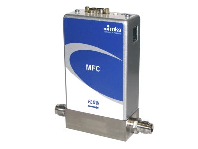
The Process flow diagrams are used to understand the process and its sequence model a process document a process ensure quality control. The MQV series features digital mass flow controllers that incorporate a thermal mass flow sensor developed by Azbil Corporation This MFC has high speed settling timewide-range controll range and low pressure loss.

MultiFlo technology allows one device to change gas types and ranges without removing the device from the system and improving actual process gas accuracy.
. KM-Series Mass Flow Meters measure gas or liquid flows even when the fluid composition is changing or unknown for pressures up to 4000 PSIA 275 bar with accuracy to 02 of reading. A qualifying symbol is graphics or text added to the basic outline of a devices logic symbol to describe the physical or logical characteristics of the device. The MKS Type 1150C Mass Flow Controller MFC is designed for precise and repeatable mass flow control of most low vapor pressure liquid or solid source materials into low pressure processes such as Low Pressure Chemical Vapor Deposition LPCVD Metal Organic Molecular Beam Epitaxy MOMBE and others.
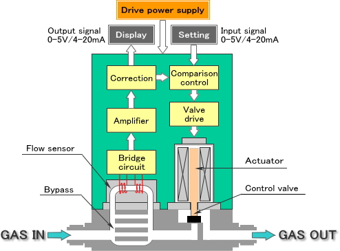
Vector symbols help develop accurate and presentation-quality diagrams. Pre-drawn flow meter symbols represent analog output flow sensor cyclonic flow meter flow element flow totalizer flow tube temperature smart magnetic etc. A mass flow controller controls a certain flow by comparing a setpoint value between 0 and 100 of its full-scale range with the measured value.
Flow controllers are also commonly seen in manufacturing to count items on a conveyor belt or. The F-series uses high speed differential pressure technology to produce an electrical signal proportional to the mass flow of air or whatever gas you want to control. At the end of this section there are several sheets contain wide.
PID is an abbreviation meaning Piping and Instrumentation Diagram. 172 rows Sample Mass Flow Controller Gas Codes. The model F4Q is a high-performance mass flow controller with high-speed responselow puressure loss and high accuracy.
After that the control valve adjusts the flow very fast by opening or closing the valve further until the setpoint is exactly reached. Industry-best range of digital mass flow meters and other products to meet widest application needs. These are fundamental to every standardized engineering project.
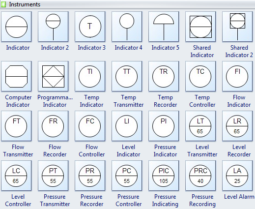
Based on your required flow rate the F-series mass flow. Piping and Instrumentation Diagrams are graphical representations of a process system. Instrumentation Symbols for PID.
They can be used in conjunction with pumps and valves in fluid flow systems in order to provide better control of flow variables. 26 libraries of the Electrical Engineering Solution of ConceptDraw PRO make your. Either an integrated display or an separate display can be selected.
It senses records and controls various process parameters to achieve best product quality at maximum economy and safety. Sometimes mass flow rate is termed mass fluxor mass current see for example Schaums Outli. Guideline for Pressure Specifications of the Mass Flow Controller 11 SEMI E56-00-1296.
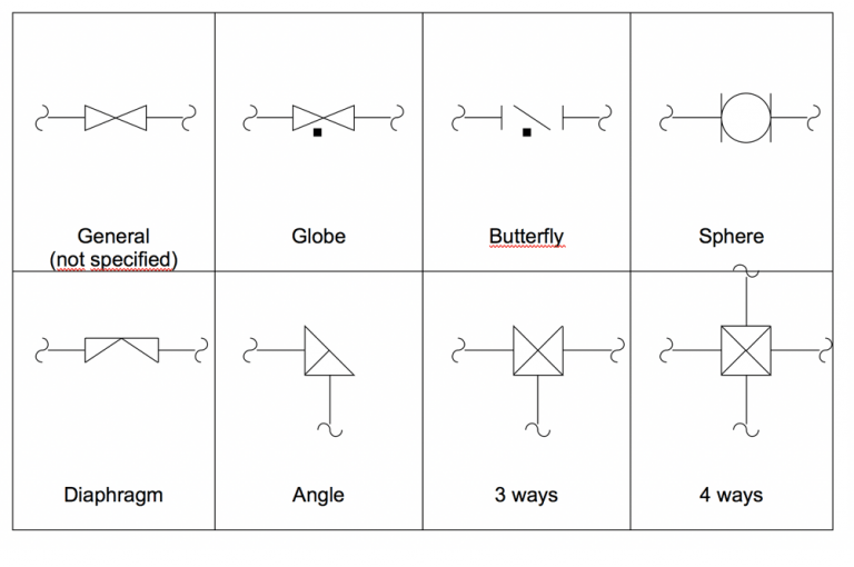
High Accuracy Coriolis Meters. However when we are being specific then any of the specific symbol for the particular flow. Digital Mass Flow Controller Model MQV_ _ _ _ The model MQV is high-performance mass flow controller with multitude functions for general industrial use.
Its unit is kilogram per second in SI units and slug per second or pound per second in US customary units. Note that FE is the general symbol for flow sensors in PIDs. Because Alicat MFCs are multivariate they measure several things like mass volume and pressure at once we built them to control on different things whil.
Magnetic Flow Meter symbol. Symbols Found on the Unit Mass Flow Controller Safety Information 2 Symbols Found on the Unit The following table describes symbols that may be found on the unit. - 3 - ANSIISA-51-2009 Preface informative This preface is included for information purposes and is not part of ANSIISA-51-2009.
Compact Digital Mass Flow Controller Model F4H. Dfc-xx-x-xxxx dfc digital mass flow controller 1st symbol 1st x range 01 0-05 mlmin 02 0-1 mlmin 03 0-2 mlmin 04 0-25 mlmin 05 0-3 mlmin 06 0-4 mlmin 07 0-5 mlmin 08 0-6 mlmin 09 0-7 mlmin 10 0-8 mlmin 11 0-9 mlmin 12 0-10 mlmin 13 0-15 mlmin 14 0-20 mlmin 15 0-25 mlmin 16 0-30 mlmin 17 0-35 mlmin 18 0-40 mlmin 19 0-45 mlmin 20 0-50 mlmin 21 0-75. In physics and engineering mass flow rate is the mass of a substance which passes per unit of time.
Flow rate F Level L Pressure P Quality Q Speed S Temperature T These codes are integrated with various symbols to distinguish between indicators recorders and in certain cases their geographical locations. From the PID flow meter symbols library you will gain a great range of high quality flow meter symbols. Use low-flow CODA Coriolis mass flow meters and controllers for high accuracy measurement of true mass flow to 02 of reading.
Test Method for Determining Accuracy Linearity Repeatability Short Term Reproducibility Hysteresis and Dead Band of Thermal Mass Flow Controllers. These two-dimensional diagrams function as a blueprint for the engineering systems design. Flow controllers are electric devices which monitor and maintain flow-rate variables typically in process applications.
This standard has been prepared as part of the service of ISA The International Society of Automation. The Process Flow Diagram is a graphical representation used to demonstrate major components of a process in an Industrial plant or manufacturer it is widely used in Chemicalpetroleum or process engineering. Instrumentation is a brain behind process control.
Standard for Mass Flow Controller and Mass Flow Meter Linearity 10 SEMI E28-00-0092. MultiFlo is offered for use with thermal thermal mass or flow sensors. The common symbol is ṁ pronounced m-dot although sometimes μ Greek lowercase mu is used.
Flow Nozzle Meter symbol. Process Monitoring Instrument Codes. This high speed flow signal is able to be used by a wide variety of Proportion-Air mass flow control valves to close the loop directly around air flow.
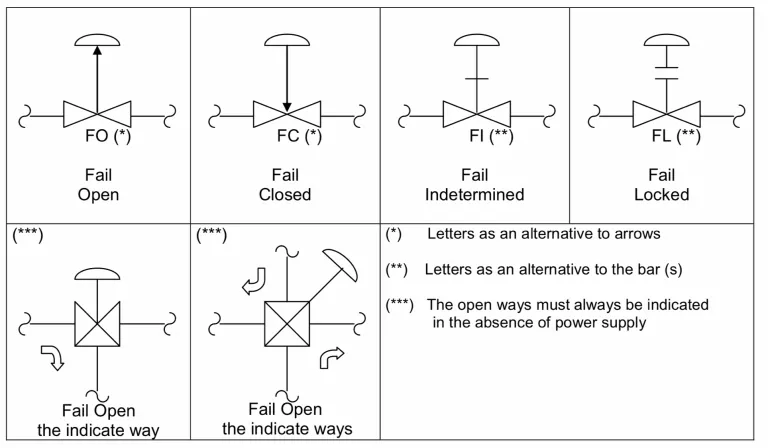
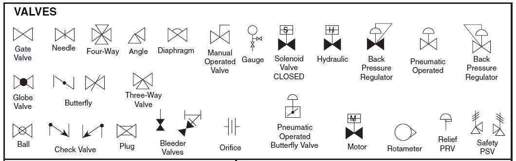
Definition of Symbols Found on the Unit On Supply IEC 417 No5007 Off Supply IEC 417 No5008 Earth ground IEC 417 No5017 Protective earth ground IEC 417 No5019 Frame. An Overview of the Common Symbols of control signals piping connections instrument bubbles valves valve actuators valve failure modes flow sensors and process equipment used in PIDs.

P Id Symbols Complete List Pdf Projectmaterials

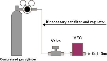
Schematic Diagram Of The Gas Mixer Examined Mfc Mass Flow Controller Download Scientific Diagram
Mass Flow Controller C F Fcon Co Ltd

A Schematic Of The In Situ Volatile Hydrocarbon Gas Chromatographic Download Scientific Diagram
P Id Symbols Complete List Pdf Projectmaterials
Mass Flow Controller C F Fcon Co Ltd

List Of Instrument Symbols In Pid Paktechpoint
P Id Symbols Complete List Pdf Projectmaterials
Flow Control Valve Electric Potential Difference Relief Valve Hydraulics Others Angle Cartridge Electric Current Png Pngwing
Process Flow Diagram Symbols And Their Usage Edraw
Control Flow Diagram Png Images Pngwing
Process Flow Diagram Processdesign
P Id Symbols Complete List Pdf Projectmaterials
4 2 Piping And Instrumentation Diagram Standard Notation Engineering Libretexts
Multi Gas Multi Range Elastomer Sealed 5 50 000 Sccm Mass Flow Controllers

Datei Symbol Flow Control Valve Svg Wikipedia

Datei Symbol Flow Control Valve Svg Wikipedia

Kurt J Lesker Company Mks Gm100a Digital Mass Flow Controller Vacuum Science Is Our Business
Fppdl Lesson 10 Symbols Used For Food Plant Design And Layout
